110-series Hardware Platform Guide
The Airwall 110 platforms are small form factor industrial security appliances that facilitate private overlay networks between customer-provided equipment and devices. This document contains important operating information, specifications, and installation instructions.
Models
| Part Number | Model | Cellular | Eth Ports | Serial Ports |
|---|---|---|---|---|
| PLF-0138-01 | Airwall 110e | No | 2 | 2 |
| PLF-0140-01 | Airwall 110g | Yes | 2 | 2 |
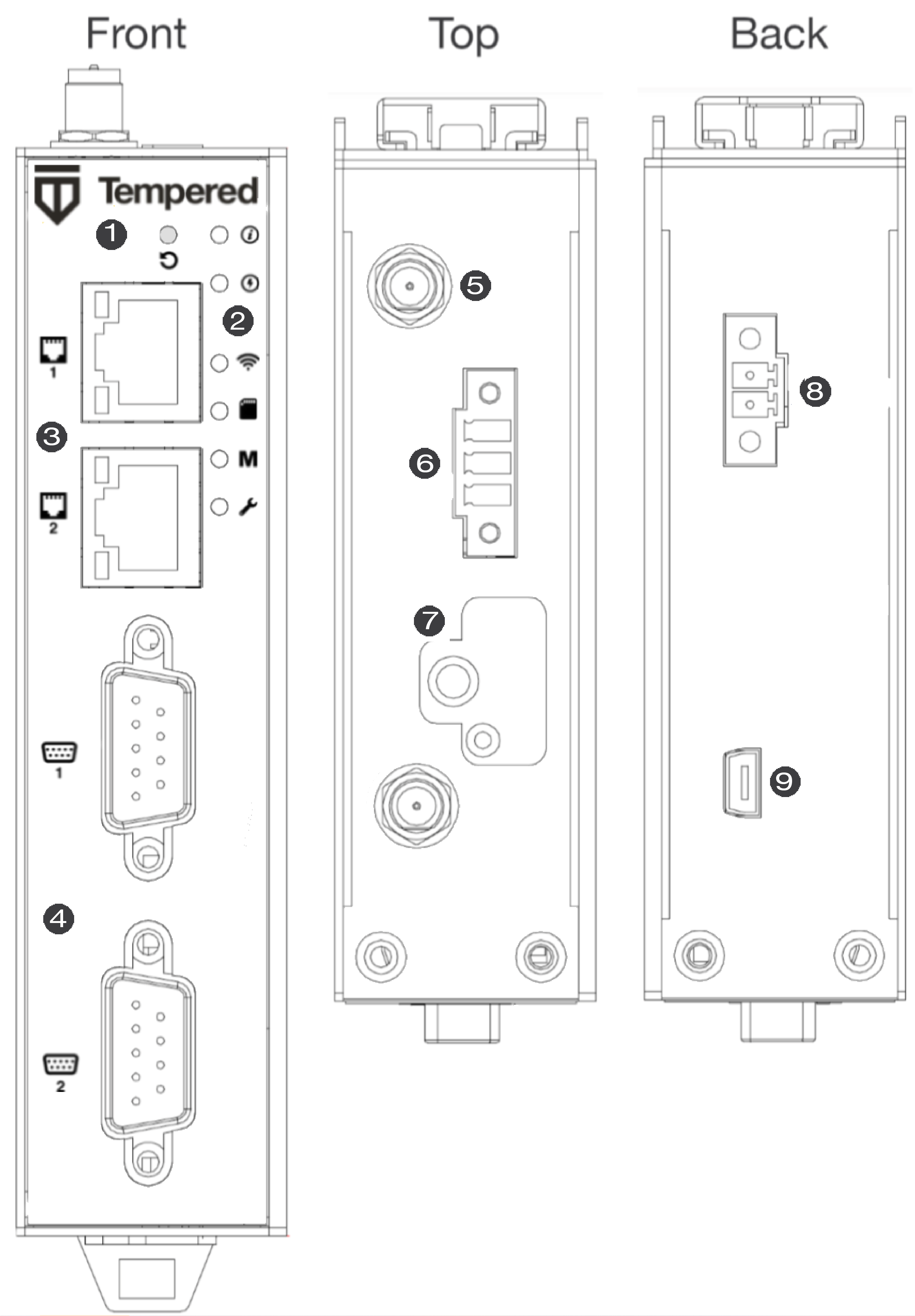
Panel Layouts
 |
|
Quick Start
- Plug in the Airwall Gateway – Locate in an area that complies with its safe operating guidelines, and then plug it in or apply power.
- Connect to your network - Using Port 1, connect the Airwall Gateway to a network where it can reach the Conductor.
- Provide the Conductor address - There are three ways to configure the Conductor address on the 110-series Airwall Gateways:
- Test your connection to the Conductor
– Check in Diagnostics mode, under Airwall Conductor, if the Conductor shows as Reachable, or using the console port, ping the conductor from
the Airwall Gateway:
ping my-conductor.tempered.com - Connect to devices – Connect the devices you want to protect to the Airwall Gateway on Port 2.
Status LED Codes
| State | LED Pattern | State | LED Pattern |
|---|---|---|---|
| Normal Operation | On Steady | No Conductor Connection | O O O O = = O O = = |
| Conductor Blink | O O = = | System Error | O O O O = = O O O = = |
| Missing Identity | O O O = = O = = | Secure Network Error | O O O O = = = |
| Factory Reset | O O = = O = = | No Shared Network | O O O O = = O = = |
| Diagnostic Mode |
O = O = (fast blink) |
Firmware Download | O O O = = O O = = |
| Firmware Update | O O O = = = | ||
| Key: O is on, = is off | |||
Wiring
Power Inputs
This device supports one power supply. The connector for PWR 1 is located on the terminal block on the top of the unit.

Step 1: Insert the negative DC into the V- terminal and the positive DC into the V+ terminal.
Step 2: To keep the DC wires from pulling loose, use a small flat-blade screwdriver to tighten the wire-damp screws in the front of the terminal block connector.
Serial Connector
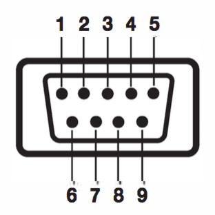
| Pin # | RS-232 | RS-422 | RS-485 |
| 1 | TX- | Data- | |
| 2 | RxD | TX+ | Data+ |
| 3 | TxD | RX+ | |
| 4 | RX- | ||
| 5 | GND | GND | GND |
| 6 | |||
| 7 | RTS | ||
| 8 | CTS | ||
| 9 |
SIM Card Orientation
Insert the SIM card with the angled corner up, as shown in the first picture.
Correct:
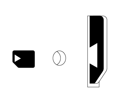
Incorrect:

Multi-Purpose Button
Also called the Reset button, the multi-purpose button provides two different functions, depending on how long it is pressed and held.
| Press Length | Instructions | Function |
|---|---|---|
| Short Press | Press for 5 seconds and release. The Status LED will blink steadily. | Places the Airwall Gateway in Diagnostic mode. |
| Long Press | Press for at least 8 seconds and release. The Status LED will blink in a 2 flash, 1 flash pattern. | Resets the Airwall Gateway to factory defaults. |
Troubleshooting
If an Airwall Gateway is online, you can use the Conductor to download a packet capture file, a diagnostic report, or a support bundle for troubleshooting. Log in to the Conductor with a system administrator or network administrator account, then go to the Airwall Gateway's Diagnostics page: Select Airwalls, choose the one you want from the list, then click Diagnostics.
- On the Airwall Gateway's Diagnostics page, begin a packet capture by clicking Start Packet Capture.
- Stop the packet capture by clicking Stop Packet Capture.
You receive a download link once the Conductor has finished creating the packet capture .pcap file. View the .pcap file using any packet-capture and proto- col-analysis tool, such as Wireshark.
- On the Airwall Gateway's Diagnostics page, you can put it into diagnostic mode and download a diagnostics report. If the Airwall Gateway's is offline, you can put it in Diagnostics mode to download the report.
- Create your report by clicking Request a diagnostic report.
You receive a download link once the Conductor has finished creating the report .txt file. Review the diagnostic report for a high-level look at the overall health of the Airwall Gateway.
A support bundle .pkg file is an encrypted archive that facilitates technical support by Tempered.
- On the Airwall Gateway's Diagnostics page, you can put it into diagnostic mode and download a support bundle. If the Airwall Gateway is offline, you can put it in Diagnostics mode to download the support bundle.
- Create a support bundle by clicking Request a support bundle.
- When the support bundle .pkg file is ready, download the file and send it as an email attachment to Customer Success
Fault Relay
This device also has a normally-open relay contact that is connected when the device is fully functional and has underlay connectivity. The relay disconnects when communication via this device is not possible. Connect your custom circuitry bearing in mind the following maximum ratings:
- Voltage: 220 VDC /240 VAC, Max current2.0A
Specifications
|
Airwall 110 Series |
|
|---|---|
|
Ethernet Ports |
2 x 10/100 Mbps RJ-45 ports, auto MDI/MDIX |
|
Console Port |
1 x micro USB |
|
Controls |
1 x multi-purpose button (actuated with pin) |
|
Indicators |
1x Power 1x Status 1x Map / Conductor 1x Diagnostic mode 1x Cellular Link (110g) 1x SIM card (110g) |
|
Relay |
Voltage: 220V DC/250V AC, Max current 2.0A |
|
DC Power Input |
DC 9-48V, 0.55A-0.1A Over-voltage protection Reverse-polarity protection |
|
Storage Temp range |
-45° to 85° C (-49° to 185° F) |
|
Operating Temp range |
-40° to 70° C (-40° to 158° F) |
|
Operating humidity |
5% to 95% (non-condensing) |
|
Dimensions |
31mm W x 100mm D x 125mm H 1.22in W x 3.94in D x 4.92in H |
|
Mounting |
DIN-rail, desk-mount |
|
Weight |
290g (10.23 oz) |
|
Serial Interfaces |
|
|---|---|
| Protocols | RS-232, RS-485, RS-422 |
| Connector | 2 x DE-9M |
| Cellular Connectivity (110g) | |
|---|---|
| SIM card | 1x micro (3FF) Push-Push SIM card slot |
| 3G | DC-HSDPA Category 24. 42mbps DL max HSUPA Category 5. 5.76Mbps UL max 24dBm+1dB/-3dB maximum transmit power |
| 4G | LTE Category 4: 1.4 – 20MHz bandwidth FDD 150mbps DL, 50mbps UL max TDD 130mbps DL, 30mbps UL max 23dBm±2dB maximum transmit power |
| 3G bands | WCDMA B1, B2, B4, B5, B6, B8, B19 |
| 4G LTE FDD bands | B1, B2, B3, B4, B5, B7, B8, B12, B13, B18, B19, B20, B25, B26, B28 |
| 4G LTE TDD bands | B38, B39, B40, B41 |
| Regulatory approvals | |
|---|---|
| Global | IECEE CB Scheme safety |
| European Union | LVD, EMCD, RoHS, REACH, WEEE RED (110g) |
| United States | FCC Part 15B Class A, cULus, FCC Radio |
| Canada | ICES-03 Class A, cULus, ISED/IC Radio |
| Japan | VCCI, JATE (110g), TELEC (110g) |
| Australia | ACMA TLN 2015, RLN 2014, EMR LN 2014 (110g) ACMA EMC LN 2017 (110e, 110g) |
| New Zealand | Radio Standards Notice 2020 (110g) EMC Standards Notice 2019 |
Maximum approved antenna gain (dBi, peak)
| Band | Uplink Freq (MHz) | USA | Canada | Japan |
|---|---|---|---|---|
| LTE B12 | 699 – 716 | 8.70 | 7.76 | N/A |
| LTE B28 | 703 – 748 | N/A | N/A | 3.00 |
| LTE B13 | 777 – 787 | 9.16 | 8.09 | N/A |
| LTE B5, B19, B20, B26, B18, WCDMA VI | 814 – 849 | 9.36 | 8.25 | 3.00 |
| LTE B8 | 880 – 915 | N/A | N/A | 3.00 |
| LTE B3, B4 | 1710 – 1785 | 5.00 | 5.00 | 3.00 |
| LTE B2, B25, B39 | 1850 – 1920 | 8.00 | 8.00 | N/A |
| LTE B1 | 1920 – 1980 | N/A | N/A | 3.00 |
| LTE B7, B38, B41 | 2496 – 2690 | 8.00 | 8.00 | 3.00 |
Hereby, Tempered Networks, Inc declares that the radio equipment type Airwall 110g is in compliance with the Directive 2014/53/EU. The full text of the EU declaration of conformity is available at the following internet address:https://repo.tempered.io/DoC/110.
The Airwall-110e and Airwall-110g can be used in all EU Member States.
This device complies with Industry Canada’s license-exempt RSSs. Operation is subject to the following two conditions: (1) This device may not cause interference; and (2) This device must accept any interference, including interference that may cause undesired operation of the device.
This equipment complies with FCC and ISED radiation exposure limits set forth for an uncontrolled environment. This equipment should be installed and operated with minimum distance of 20cm between the radiator and your body and must not be co-located or operating in conjunction with any other antenna or transmitter.
If this device is installed with an antenna other than the type included with it, you must select an antenna and cabling system that respects the maximum antenna gain listed in the tables. If your selected antenna does not meet these criteria, you may void your legal authority to operate this equipment.
Parts List
|
WALL-HW-110e WALL-HW-110g included with above:
|
Power Supply: ACC-HW-110-PSU-25W AC Power cables: ACC-HW-PWR-C13-NA, (North America) ACC-HW-PWR-C13-JP, (Japan) ACC-HW-PWR-C13-AU, (Australia / New Zealand) ACC-HW-PWR-C13-UK, (UK, Singapore, Malaysia) |
Safety and Warnings